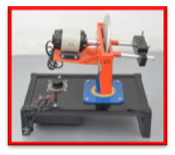
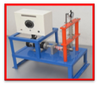
1.Motorized Gyroscope Apparatus
The equipment is used for various controls in high technology vehicles. For minimizing rolling yawing and pitching of ship or air craft Gyroscope is used. Balloons use gyroscope for controlling direction, Gyroscope has application in space craft, space platforms. Thus study of Gyroscope is of high importance for any engineering student. The motorized Gyroscope consists of a disc rotor mounted on a horizontal shaft rotating in the ball bearings of one frame. The rotor shaft is coupled to a motor mounted on a trunion frame having bearings in a yoke frame which is free to rotate about vertical axis. Thus the disc can be rotated about three perpendicular axes. Angular scale and pointer fitted to frame helps to measure precision rate.
Features:
• Demonstration of relationship between applied torque and precession rate alongwith direction of rotation.
• Gyroscopic couple easily varied by weights
.
• Precisely balanced rotor.
• Useful to verify the relationship #T = lw.wp
Specifications:
• • Disc rotor - 30 cm. dia, 10mm thick. approx.
• Drive - FHP, AC/DC single phase motor
• Dimmerstat - 2 Amps.
• Weight set.
Experimentation:
• Observation of Gyroscopic behavior (Two lows of stability)
• Experiment justification of the education.T = lw.wp for calculating the Gyroscopic couple by
• observation and measurement of results of independent variations in applied couple T and precession wp.
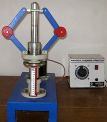
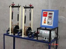
2.Universal Governor Apparatus
The equipment is designed to study various governors. The normally used to control the speed. The unit consists of a main spindle driven by a variable speed motor mounted on a base plate. The spindle is driven by belt and pulley system. The optional governor out of four governor assemblies can be mounted on spindle. The spindle speed can be controlled by speed control unit provided. A graduated scale is provided to measure the displacement of sleeve.
The centre sleeve of portal and proell governors incorporates a weight sleeve to which weight may be added. The Hartnell governor provides means of varying spring compression level. This enables the Hartnell governor to be operated as a stable or unstable governor.
Specifications:
• Drive unit - PMDC motor, 1/6 HP, 1500 RPM
• Speed control unit working on 230V AC supply with 0-200V DC output
• Belt and Pulley system to give spindle speed 100 to 500 rpm.
• Governor Mechanism with springs and weights for following Governors.
• Watt Governor
• Porter Governor
• Hartnell Governor
• Procell Governor
• For all types of Governors.
Experimentation:
• Determination of characteristic curve of sleeve position against speed of spindle.
• Derivation of actual controlling force curves from the above and comparison with theoretically predicted force curve.
• Porter and Proell Governor - The effect of varying mass of sleeve.v Hartnell Governor - The effect of varying initial spring compression.
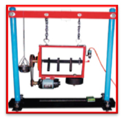
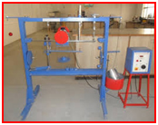
3.Static & Dynamic Balancing Apparatus
The equipment is cable to experiment balance a rotating mass system and to verify the analytical relations.
The equipment consists of a steel shaft fixed in a rectangular frame. A set of four blocks with a clamping arrangement is provided. For static balancing, each block is individually clamped on shaft and its relative weight is found out using cord and container system in terms of number of steel balls.
For dynamic balancing, a moment polygon is drawn using relative weights and angular and axial positions of blocks are determined. The blocks are clamped on shaft is rotated by a motor to check dynamic balance of the system.
The equipment is provided with angular and longitudinal scales and is suspended with chains for dynamic balancing.
Specifications:
• Drive Motor, Universal Motor
• Balancing Weights - 4 Nos. with different size eccentric mass for varying unbalance.
• Cord & Container with steel balls for relative weight measurement.
Experimentation:
• Static balancing of system using steel balls.
• Dynamic balancing of a simple rotating mass system.
• Observation of effect of unbalance in a rotating mass system.
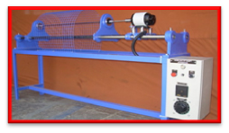
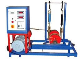
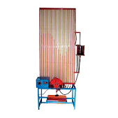
4. Whirling of Shaft Apparatus
The equipment consists of a base upon which bearing holders and drive motor can be mounted. Different bearings can be fitted in bearing blocks to have different end conditions as, both end fixed, one end free, one end fixed etc. A varied speed motor is provided to drive the motor along with speed control unit. The equipment is useful to demonstrate the phenomenon of whirling of shaft with single rotor. As this test is destructive, after the test shaft cannot be used again, hence this unit only demonstrates the principle.
Specifications:
• Test shaft - 3.17mm, 4.75mm dia. 1 mt. long approx.
• Bearings to provide following end conditions - • Both end fixed.
• One end fixed one end free.
• Drive motor - 1/6 HP, 6000 RPM.
• Speed controller unit.
5.Cam Analysis Apparatus
The equipment is designed to study the cam profile and performance of Cam and Follower system. The equipment consists of a shaft supported in ball bearing and driven by variable speed PMDC Motor. Various types of Cams can be mounted on this shaft. A push rod assembly is supported vertically and various types of followers can be attached to this push rod. A dial gauge is provided to plot the follower displacement with respect of rotation of Cam. Provision is also made to vary the weight or spring compression of follower assembly so that effect of follower eight or spring force on jump can be studied. With the help of stroboscope (not included in scope of supply).
Specifications:
• Cams - Tangent and Circular type.
• Follower - Mashroom, Roller and Knief edge.
• Weights - 100 gm, 200 gm
• Compression spring.
• Motor - variable speed DC motor, 1/8 HP.
• Speed control unit
• Dial gauge
• Cams & followers are suitably hardened to reduce wear.
Experimentation:
• Plotting and analysis of the X-0 curve.
• Follower bounce can be observed using stroboscope.
• To study the effect of follower weight on bounce.
• To study the effect of spring compression on bounce.
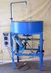
6.Coriollis Component of Acceleration Apparatus
The apparatus is designed to study coriollis component of Acceleration of a slider crank mechanism. The apparatus uses hydraulic analogue to represent the rotating slider. It consists of a rotating block with two arms in opposite direction.
The tubes can be rotated at various speeds by using a swinging field motor which also acts as a dynamometer to measure torque applied to rotating tubes. A perspex window on top cover helps to visualise the process. Rotameter is used to measure water flow rate through tubes. Water is circulated by small monoblock pump.
Specifications
• Main tank with fibre glass lining.
• Rotating arms 9/6 mm dia, 300mm long.
• Motor - Swinging field, DC, 0.5 HP
• Rotameter
• Monoblock pump
• Control panel comprising of :
• Speed Control Unit
• Speed Indicator
• Necessary switches.
• Rigid support frame.
Experimentation:
Coriollis Component of Acceleration can be determined at various speeds of rotation and water flow rates.
7.Vibration Table's Apparatus
The equipment has been designed to perform and verify the principals involved in study of vibrations. It consists of a basic frame and various components and sub-assembled designed for quick changeover and easy assembly of number of experiments in vibration. A speed controller unit is provided for forced vibration experiments. With this unit following 8 experiments can be conducted.
8.Slip & Creep In A Flat Belt Apparatus
The equipment consists of a base Slip & Creep in a belt and drive motor can be mounted. Different forced can be fitted in moter to have different end conditions as, both end fixed, one end free, one end fixed etc. A varied speed motor is provided to drive the motor alongwith speed control unit.
9.Journal Bearing Apparatus
The apparatus consists of a plain steel shaft encased in a bearing and directly driven by a small electric motor. The bearing is freely supported on the shaft and sealed at motor end. The motor speed is precisely controlled by control unit and can be run in both directions. The bearing contains twelve equi-spaced pressure tappings around circumference and four along the axis. All are connected by light flexible plastic tubes to the manometer so that the pressure head of all sixteen points can be observed at a time. The bearing can be loaded by attaching weights to the arm supported beneath it.
10.Epicyclic Gear Train And Holding Torque Apparatus
input and output shaft through the epicyclic gear train. The input (driving) shaft carries an arm and pin on which the compound gear wheel is free to remove and it meshes with the fixed wheel and the wheel is keyed to the output (driven) shaft.
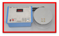
11.Drilling Tool Dynamometer Apparatus
This is a armed wheel type strain gauge drill tool dynamometer designed to measure thrust and torque during drilling operation. This Dynamometer is suitable for drilling a holeupto20mm size in M.S. With this Dynamometer students can study the change in these forces by varying Speed, Cut and Feed.
Features:
• Rigid construction
• Sensitive transuding and amplifying system for accuracy in force measurement.
• Digital Force Indicator.
• Range of force measurement in coordinate direction : 0 to 200 kg
• Use of cutting fluid during operation is possible.
Scope of supply:
• Mechanical sensing unit and working piece holder with strain gauge.
• Control panel housing Digital Force Indicator to measure both forces simultaneously, balancing potentiometer, connecting cables, necessary switches, fuses and screen printed front plate. The Dynamometer is calibrated at factory with the help of proving ring and reading are directly in the form of kg.

12.Lathe Tool Dynamometer Apparatus
This is a strain gauge type two component lathe tool dynamometer designed to measure vertical and horizontal forces on tool while orthogonal cutting process. The unit is in two parts one is mechanical sensing unit or tool holder, which can be mounted on the top of the cross slide after removing swivel base and compound slide of a lathe and Digital Force Indicator. With this Dynamometer students can study the change in these forces by varying Speed, Cut and Feed.
Features:
• Rigid in construction
• Sensitive transuding and amplifying system for accuracy in force measurement.
• Compact Digital Force Indicator.
• Use of cutting fluid during operation is possible.
Scope of supply
• Mechanical sensing unit or Tool holder with strain gauge with H.S.S. tool of 1/2" size.
• Control panel housing Digital Force Indicator to two forces simultaneously, balancing
• potentiometers, connecting cables, necessary switches, fuses and polycarbonate front plate.
• Range: 0 to 200 kg.
• The Dynamometer is calibrated at factory with the help of proving ring and reading are directly in the form of kg.
13.Milling Tool Dynamometer Apparatus
This is a simple and easy to understand set-up to study the behavior of cutting forces during milling operation in three directions. With this unit user can evaluate cutting forces for varying cutting depth, speed and feed. The unit works on standard method of Octagonal ring with strain gauges. It is in two parts one mechanical set-up consisting a set of octagonal rings sandwiched between two M.S. plates with Strain gauge fixed on it. This set of octagonal ring transmits the relevant data to the force indicator during milling operation.
Features:
• Rigid in construction
• Compact unit
• Assessment of cutting forces by given due consideration to various parameters like depth of cut, material, speed and feed.
• Easy in handling.
• Digital Force Indicator to measure three forces simultaneously.
Specifications:
• Three channel Digital Force Indicator with balancing potentiometers and polycarbonate front plate.
• Range of force measurement in coordinate direction: 0 to 200 kg.
• Overall size of mechanical unit: 300x300mm.
• Power source: 230V +/-10%, 50 Hz.